
A number of commonly used low-speed and general aviation aerofoils are analysed both in-ground-effect and out-of-ground effect using 2D RANS CFD. These analyses are verified against 2D panel method. Data is presented as-is with no conclusion drawn.
NOMENCLATURE
IGE – In Ground Effect
OGE – Out of Ground Effect
GEV – Ground Effect Vehicle
GA – General Aviation
x/c – Distance normalised by chord
h/c – Height normalised by chord
RANS – Reynolds Averaged Navier-Stokes
CFD – Computational Fluid Dynamics
STL – Steroligography (triangulated suface file)
AoA – Angle of Attack
RE – Reynolds Number
y+ – Dimensionless wall distance
BACKGROUND
Theoretical and experimental data for wing sections has been readily available for decades, Abbott and Von Doenhoeff’s [1] remains an industry standard. However, there is no access to similar data with respect to aerofoils in ground effect.
The intent of this paper is not to present any detailed analysis or conclusion, in fact no conclusions are to be drawn. The data is to stand by itself in the hope that it may be of use as a reference for more advanced work. In addition to the appendices to this paper the author has made available the raw data online. [2]
METHODOLOGY
The process relies on open-source programmes, starting with the creation of a 2.5D wing (i.e. extruded 2D section) and finishing with post-processing of a finite-volume RANS solution.
The results are generated as follows:
- Surface geometry (STL) created using OpenVSP. [3]
- Bespoke Python script used to automate the creation of meshes.
- -4 to 18° AoA in 2° increments
- Each incidence OGE
- Each incidence IGE at h/c 0.25 to 2 in quarter chord increments.
- Analyses run in OpenFOAM 2.3.1 [4] and verified against JavaFoil. [5]
- Post processing in Paraview. [7]
Each analysis is modelled at RE=4.1×10^5, this is fairly representative for GEVs. (S-A and wall functions) (flat plate thickness). The aerofoils modelled are listed in Table 1. The AoA is modified by rotating the aerofoil about (0.25, 0), a point located on the ground, as highlighted in Figure 1, thus matching the methodology of JavaFoil.
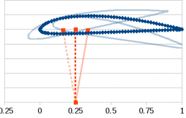 Figure 1 – Location of rotation point for AoA
KNOWN LIMITATIONS
There is no wind-tunnel data available to validate any data presented in this report. Due to the advances in automotive and race-car modelling, wind-tunnels with moving ground are now fairly common. However, a wide-ranging public-domain set of data for GEV sections does not exist. This is presumably because of a lack of commercial and research interest in GEVs. Consequently the data provided in this report is not validated, instead it is only verified against the panel method from JavaFoil.
Due to the limited control available in snappyHexMesh – the hex-dominant mesh generator supplied with OpenFOAM – the boundary layer mesh for each aerofoil is not ideal because boundary layer growth is not accounted for. Each aerofoil has been modelled with a boundary layer mesh of the depth equivalent to an analytical flat-plate at quarter chord.
REFERENCES
I. H. Abbott and A. E. Von Doenhoff, Theory of Wing Sections. Dover, 1949.
J. Moller. (Feb 2015). glypo.com GEV page [Online]. Available: http://glypo.com/gev
NASA. (Feb 2015). OpenVSP [Online]. Available: http://www.openvsp.org
OpenFOAM Foundation. (Feb 2015). OpenFOAM [Online]. Available: http://www.openfoam.org
Kitware. (Feb 2015). ParaView [Online]. Available: http://www.paraview.org
Mh aerotools. (Feb 2015). JavaFoil [Online]. Available: http://www.mh-aerotools.de/airfoils/javafoil.htm
Mh aerotools. (Feb 2015). JavaFoil Validation and Accuracy [Online]. Available: http://www.mh-aerotools.de/airfoils/jf_validation.htm
Y. Zhang, Flow simulation over 2D airfoil using OpenFOAM. TU Delft, 2012.
Creative Commons. (Feb 2015). Attribution-NonCommercial-ShareAlike 4.0 International [Online]. Available: http://creativecommons.org/licenses/by-nc-sa/4.0/